ESP8266 ติดต่อ water flow sensor เพื่อวัดการอัตราการไหลของน้ำ หรือ ของเหลว
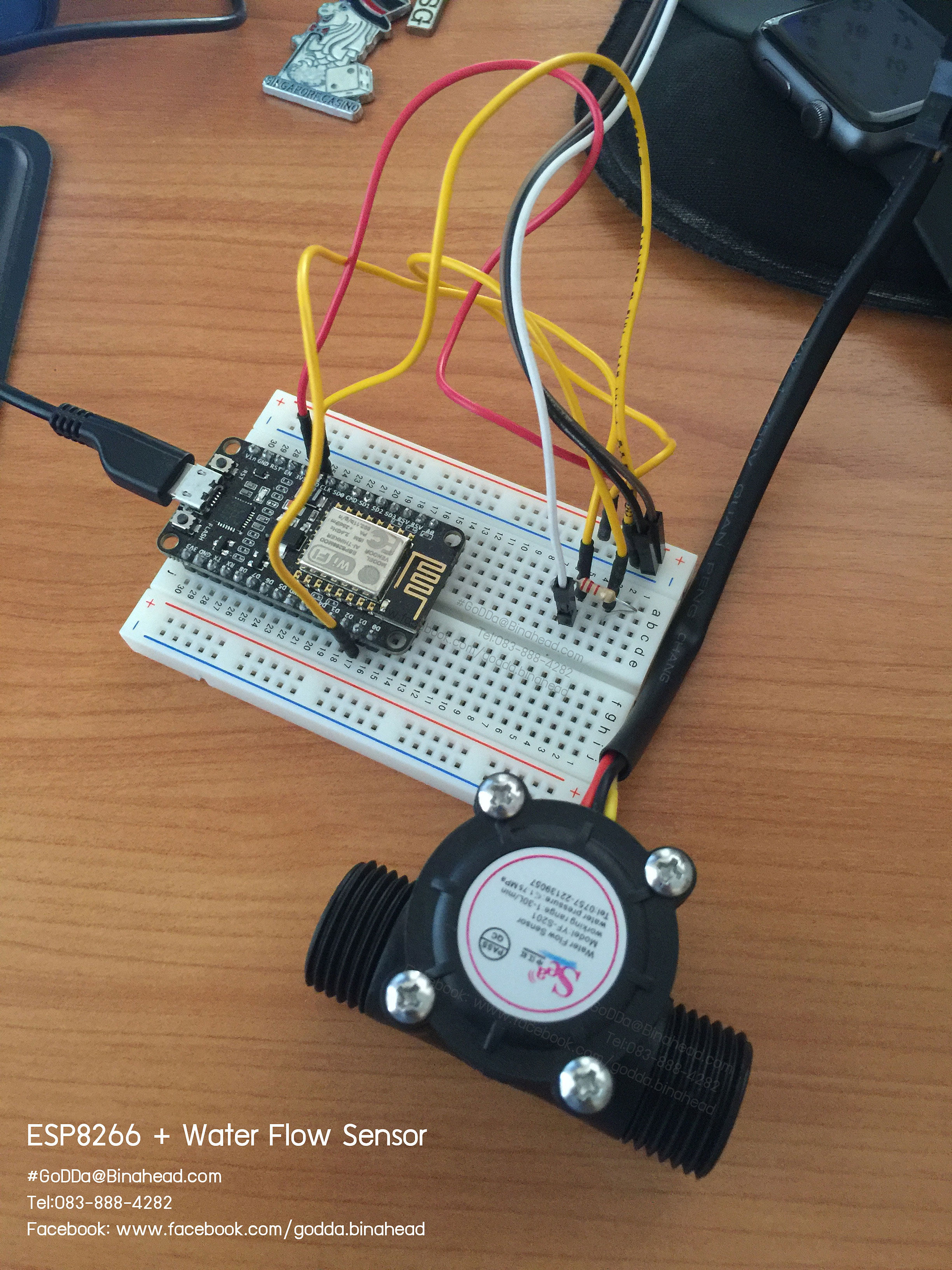
วันนี้มาปัดฝุ่นเว็บด้วยบทความที่เกิดจากความสงสัย(คัน)จากที่มีเพื่อนสมาชิกกลุ่ม ESP8266 Thailand ใน Facebook ขมาสอบถามเรื่องการเขียนโปรแกรมให้เจ้า ESP8266 ติดต่อกับเซนต์เซอร์วัดอัตราการไหลของน้ำ โดยที่ลองทำกับ บอร์ด Arduino แล้วสามารถใช้งานได้แต่ยังไม่สามารถประยุกต์กับเจ้า ESP8266 ได้เป็นผล ผมจึงลองไปซื้อเจ้าเซนเซอร์ตัวดังกล่าวมาเพื่อทดสอบ โดยอ้างอิง code ตัวอย่างของ Arduino ในการประยุกต์
// reading liquid flow rate using Seeeduino and Water Flow Sensor from Seeedstudio.com
// Code adapted by Charles Gantt from PC Fan RPM code written by Crenn @thebestcasescenario.com
// http:/themakersworkbench.com http://thebestcasescenario.com http://seeedstudio.com

volatile int NbTopsFan; //measuring the rising edges of the signal
int Calc;
int hallsensor = 2; //The pin location of the sensor

void rpm () //This is the function that the interupt calls
{
NbTopsFan++; //This function measures the rising and falling edge of the hall effect sensors signal
}
// The setup() method runs once, when the sketch starts
void setup() //
{
pinMode(hallsensor, INPUT); //initializes digital pin 2 as an input
Serial.begin(9600); //This is the setup function where the serial port is

initialised,
attachInterrupt(0, rpm, RISING); //and the interrupt is attached
}
// the loop() method runs over and over again,
// as long as the Arduino has power
void loop ()
{
NbTopsFan = 0; //Set NbTops to 0 ready for calculations
sei(); //Enables interrupts
delay (1000); //Wait 1 second
cli(); //Disable interrupts
Calc = (NbTopsFan * 60 / 7.5); //(Pulse frequency x 60) / 7.5Q, = flow rate

in L/hour
Serial.print (Calc, DEC); //Prints the number calculated above
Serial.print (" L/hour\r\n"); //Prints "L/hour" and returns a new line
}
โดยจะเห็นว่าใน code นั้นจะมีการเรียกใช้ interrupt จำนวนหนึ่งขา เพื่อทำการอ่านสัญญาณที่ส่งมาจากตัวเซนเซอร์ซึ่งจะส่งมาในลักษณะของ สัญญาณแบบ pulse ส่วนหลักการภายในของเซนเซอร์ผมขอยกยอดไว้คุยต่อกันในคราวหน้านะครับ

ทีนี้มาดูกันว่าหากเราจะนำ code ตัวอย่างไปประยุกต์ใช้บน ESP8266 โดยในทีนี้ผมใช้ตัวอย่างเป็นบอร์ด node mcu dev kit นะครับ และใช้ Arduino IDE ในการเขียน เริ่มต้นเราต้องเข้าใจก่อนว่าขาสัญญาณที่เราต้องใช้มันอยู่ตรงไหน อย่างเช่นในตัวอย่างของบอร์ด Arduino นั้นจะมีขาให้เราใช้งานอยู่ ไม่กี่ขาซึ่งเราต้องดูจาก สเปคของ IC ที่ใช้ ซึ่งแตกต่างกันไปตามเบอร์ของบอร์ด Arduino ด้วยเช่นกัน

คราวนี้มาถึงพระเอกของเรา เจ้า ESP8266 แน่นอนมันก็มีขาที่สามารถใช้งานเป็นขาสัญญาณแบบ interrupt ได้เช่นกันแต่ก็จะแตกต่างออกไปไม่เหมือนหรือตรงกับขาของ บอร์ด Arduino โดยอ้างอิงจากเอกสารของ ESP8266
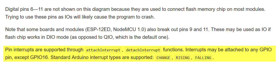
รายละเอียดการเรียกใช้งาน interrupt ผ่านขา IO ของ ESP8266 ผ่าน Arduino IDE
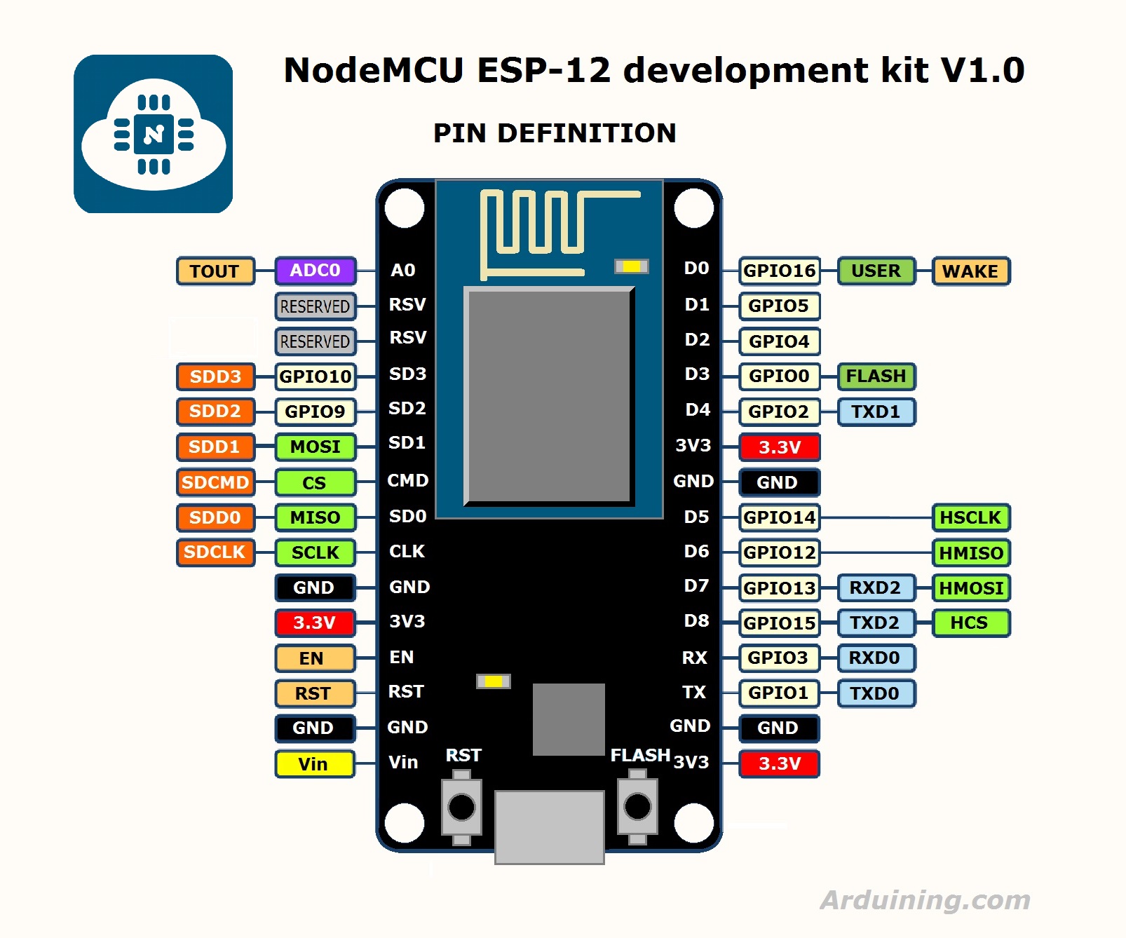
จากข้อมูลข้างต้นจะเห็นว่าเราสามารถ กำหนดให้ ขาสัญญาณ io ของ ESP8266 ให้เป็นขาสัญญาณ แบบ interrupt ได้ตั้งแต่ io-0 ไปจนถึง io-16 กันเลยทีเดียวเรียกได้ว่าจุใจกว่า Arduino บอร์ดมาก เมื่อรู้ดังนี้เราก็มาลองกำหนดขาสัญญาณให้กับ code ของเราใหม่เพื่อให้สอดคล้องกับขาสัญญาณของ ESP8266 โดยผมเลือกใช้ขาสัญญาณ io5 ในการทำงานในครั้งนี้ซึ่งบนบอร์ด dev kit จะตรงกับขา D1 สำหรับใครที่กลัวจะสับสนแนะนำให้หา Pin map หรือผังขาสัญญาณไว้ข้างตัวจะดีมากเวลาเราต้องต่อขาสัญญาณต่างๆ
เมื่อเราปรับปรุง code ของเราแล้วก็จะได้หน้าตาประมาณนี้
// reading liquid flow rate using Seeeduino and Water Flow Sensor from Seeedstudio.com

// Code adapted by Charles Gantt from PC Fan RPM code written by Crenn @thebestcasescenario.com

// http:/themakersworkbench.com http://thebestcasescenario.com http://seeedstudio.com

volatile int NbTopsFan; //measuring the rising edges of the signal

int Calc;

int hallsensor = 5;   //The pin location of the sensor

void rpm ()     //This is the function that the interupt calls

{

NbTopsFan++; //This function measures the rising and falling edge of the hall effect sensors signal

}

// The setup() method runs once, when the sketch starts

void setup() //

{

pinMode(hallsensor, INPUT); //initializes digital pin 2 as an input

Serial.begin(9600); //This is the setup function where the serial port is initialised,

attachInterrupt(5, rpm, RISING); //and the interrupt is attached

}

// the loop() method runs over and over again,

// as long as the Arduino has power

void loop ()

{

NbTopsFan = 0;     //Set NbTops to 0 ready for calculations

sei();           //Enables interrupts

delay (1000);     //Wait 1 second

cli();           //Disable interrupts

Calc = (NbTopsFan * 60 / 7.5); //(Pulse frequency x 60) / 7.5Q, = flow rate in L/hour

Serial.print (Calc, DEC); //Prints the number calculated above

Serial.print (" L/hour\r\n"); //Prints "L/hour" and returns a new line

}
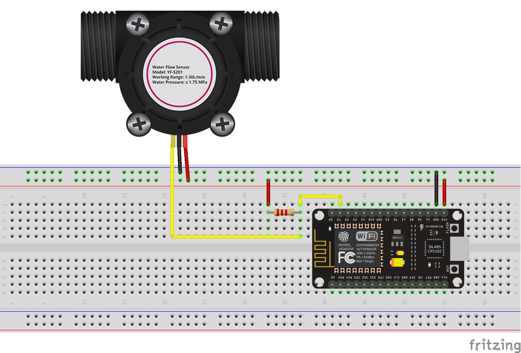
แทบจะไม่ต้องเปลี่ยนอะไรมากเน้นว่าต้องเลือกและกำหนดขาให้ถูกต้อง ที่เหลือ ไลบรารี่ของ ESP8266 จัดการให้เกือบหมด (ง่ายเว่อร์จนเกือบจะง่อยรับประทาน 555) เอาละมาว่ากันต่อคราวนี้เราก็ต้องลองของ เอ้ยลอง code ของเรากันหน่อย จัดแจงต่อวงจรตามผังดังนี้เลยครับ เพื่อทดสอบ ย้ำนะครับใครที่ใช้บอร์ดอื่นหรือ เวอร์ชั่นอื่นให้อิงตาม pin map ของรุ่นหรือเวอร์ชั่นของตัวเองนะครับทำตามผมอาจจะไม่เกิดผลได้จ้า
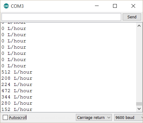
เรียบร้อยคราวนี้เราก็มาดูผลโดย มอนิเตอร์ผ่านทาง serial port จากนั้น เป่าครับ พูดจริงๆ คือเป่าครับถ้า การทำงานไม่ผิดพลาดเราจะพบความฟินที่หน้าจอของเราดังภาพที่ผมได้แนบมา นั่นคือค่าอัตราการไหลที่อ่านได้จากการหนุมของใบพัดข้างในเซนเซอร์
โอเคจบไปแล้วกับบทความสั้นฉบับรีบเขียนรีบใช้ หากท่านใดมีข้อสงสัยติดต่อมาพูดคุยถามไถ่กันได้นะครับ ยินดีให้คำตอบทุกเรื่อง(ที่รู้)จ้า…
สวัสดีครับ
[ที่มา]
- โปรไฟล์ อุปกรณ์ในโปรแกรม Fritzing
http://www.ayarafun.com/2015/07/esp8266-nodemcu-for-fritzing/
http://omnigatherum.ca/wp/?tag=fritzing
- ตัวอย่าง code เชื่อมต่อ เซนเซอร์
http://forum.arduino.cc/index.php/topic,8548.0.html
You must log in to post a comment.